Slink Filter AU/VST
Created by Alexander Berg & Michel Iseneld with Vocode and Signalsmith Audio.
About
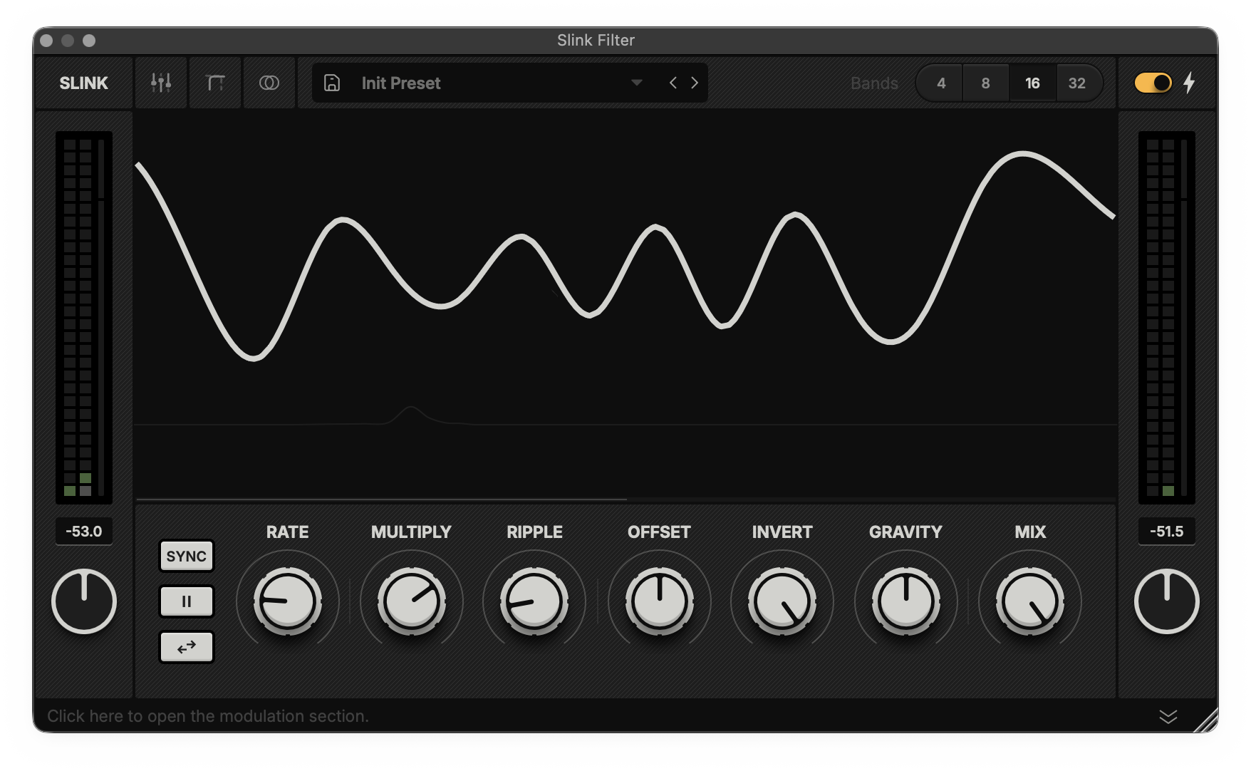
Slink Filter is an automated filter bank that creates anything from extreme spectral stereo morphing to soft tonal variations.
It unites the eye and ear into an intuitive tool that delivers fast results while allowing endless, in-depth tweaking.
How it works
Inspired by the movement of water, Slink Filter is animated by an algorithm that sends ripples through the amplitudes of up to 32 bandpass filters. These filters are divided into the left and right audio channels, at fixed frequency points, creating a unique, mono-compatible, morphing stereo effect.
The Slink engine and filter models have been optimised by Signalsmith Audio.
Minimum Requirements
Any AU or VST3 compatible host
Windows 10 or macOS 12
3 GHz processor
Most of The Information below is available as tooltips within the device
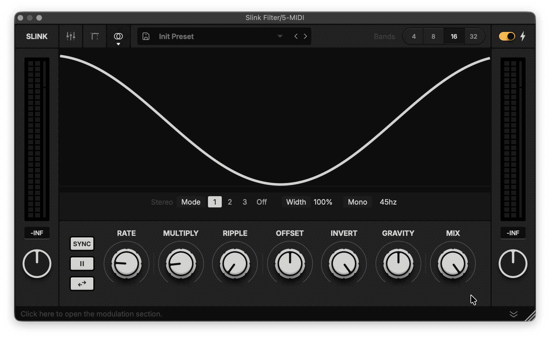
Header
The header (shown above) navigates between Slink’s different views, presets and filter options.
From left to right:
Slink logo: Displays the current size of your window as you resize it. Double-click to restore it to the default size.
Navigation: Access additional settings through these tabs. Click an active tab to return to the default view.
Band Gain View: Shows controls that adjust the maximum modulation depth for each filter band.
Area View: Contains parameters that allow you to bypass Slink’s modulation across swathes of bands and set their static levels.
Stereo View: A few parameters that govern the unit's spatial behaviour.
Preset Menu
Save: Save the current configuration as a new user preset.
Downward Arrow: Open to browse and load presets.
Sideway Arrows: Toggle between presets.
Preset folder location:
Mac: Users > [username] > Documents > Hypnus > Slink > Presets
PC: Users > [username] > AppData > Roaming > Hypnus > Slink > Presets
Filter Options
Bands: Choose between 4, 8, 16 (default) or 32 bands.
The Bolt toggles between a transparent model (off) and a more subtractive hardware-style character (on).
Hint: 32 bands AND the Bolt turned off gives a character most similar to the Max for Live version of Slink Filter.Scan
Clicking and dragging the display horizontally in the default view adjusts the Scan value, shifting the phase index of the Slink algorithm. This means that you’re able to move the wave pattern around and achieve many more different results.
Level Controls
These are located to the left and right of the Slink wave display and main control panel.
Level Meters: Shows the in- and output peak (squares) and RMS levels (thin bar next to the squares).
Peak: The display below each meter shows the highest level recorded since the unit was initiated. Click to reset.
Gain: The input gain (left) adjusts the incoming signal level before reaching the filter engine, while the output gain (right) adjusts the signal level after the filter engine processing.
Main Control Panel
From left to right:
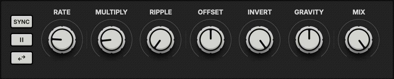
The Buttons:
Sync: Toggles the modulation rate between absolute frequency (Hz) and tempo-synced divisions (1/8, 1 bar, etc.).
Freeze: Pauses the Slink wave modulation movement.
Reverse: Inverts the direction of the Slink wave's movement.
Rate: Sets the movement speed of the Slink wave.
When synced, right-click to add dotted or triplet values.
Multiply: Increases the number of wave cycles.
Ripple: Introduces a sinusoidal ripple effect to the Slink wave.
Offset: Shifts the wave’s phase position for manual control of a cycle.
Invert: Attenuates or inverts the modulation depth of the Slink wave.
Gravity: Simulates gravitational force on the wave.
High values may open alien wormholes, while lower ones tend to introduce gentler slitherings.
Mix: Blends the processed signal with the dry input.
Hint: Right-click parameters 2-8 to assign them a modulator.Hint: By setting the Rate to 0 and connecting a modulator to Offset, you introduce a new global shape to the Slink wave.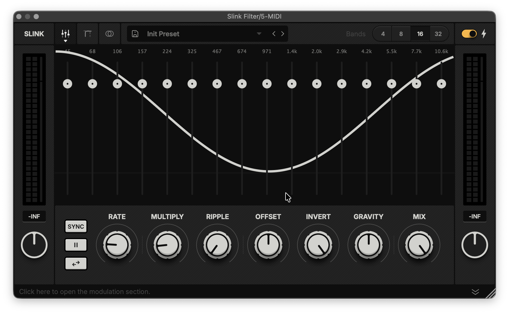
Band Gain View
In this view, you can modify the maximum modulation value for each filter band, allowing you to set specific gain levels and fine-tune your patches with high precision.
Hint: Hold Option and click anywhere on a band to reset its value.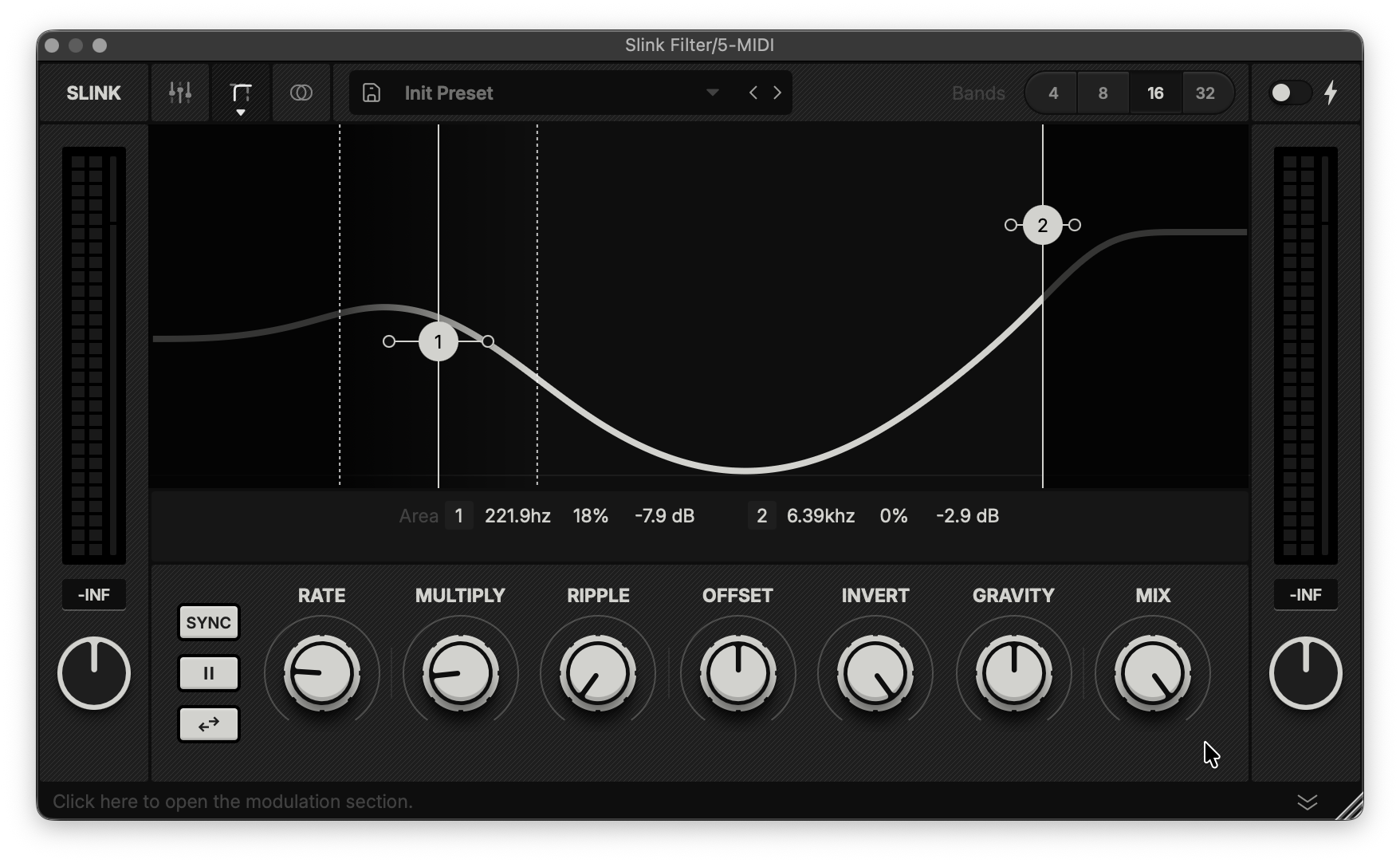
Area View
These settings allow you to bypass the Slink engine’s global modulation for bands in specific areas and adjust their static level.
Cutoff: Sets the frequency (Hz) above or below which modulation is bypassed.
Slope: Adjusts the transition (%) between the modulated and bypassed areas.
Gain: Sets the static level (dB) for filter bands in the bypassed area.
The nodes on the screen control the Cutoff and Gain parameters, while the horizontally adjustable handles adjust the Slope.
Stereo View
These settings manipulate the stereo output of Slink.
Mode: Select a spatial algorithm or disable stereo processing.
Width: Adjusts the stereo spread. 0% sums the signal to mono.
Mono: Sums low frequencies to mono under the selected cutoff.
We are developing a stereo visualiser for the main display that will provide these parameters with improved optical feedback.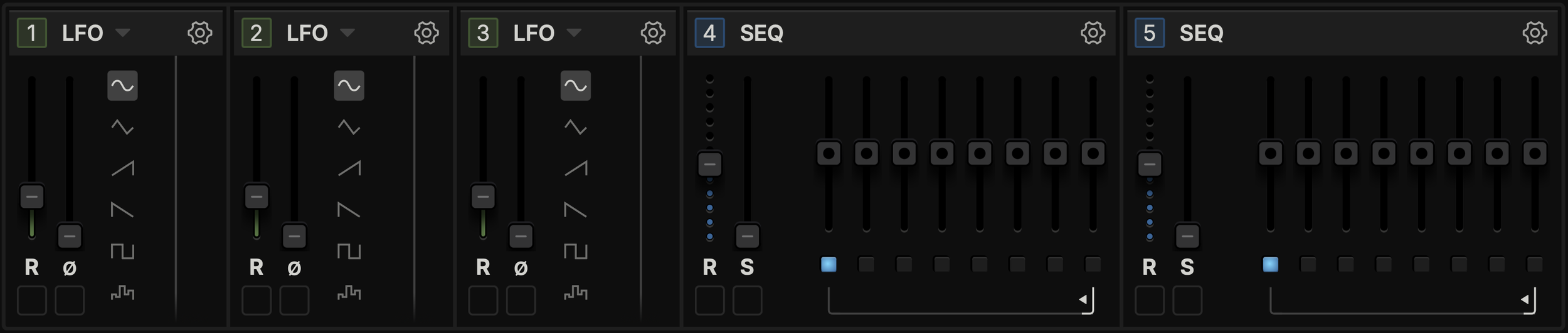
Modulation Section
The modulation section lets you add more movement to your Slink project.
Drag the number of a module to connect it to a source (image below).
Type: Indicates the type of module currently available. Clicking the title or the downward arrow next to it opens a menu to swap it for another modulator type.
Cogwheel: Configure sync and trigger behaviour for this modulation source.
Hint: You may also click a module's number, then click an input (shown below) to make a connection. 
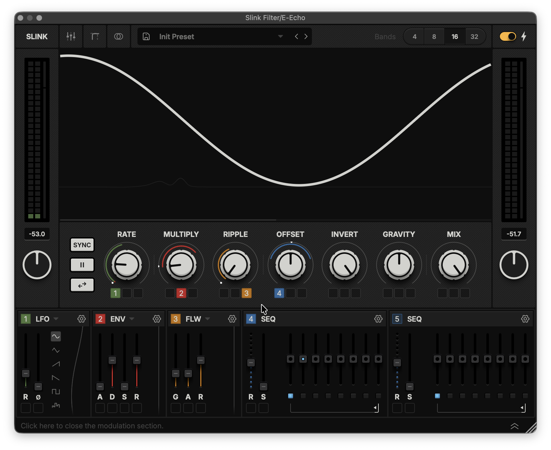
Hint: Right-click the coloured connector icons under each destination to access additional features, such as toggling between uni- and bipolar modes.Envelope
Attack: Sets the speed at which the envelope reaches its peak value.
Decay: Sets the speed at which the envelope drops from the peak to its Sustain value.
Sustain: Sets the modulation level maintained while a trigger is held.
Release: Sets the speed at which the envelope drops to zero once a trigger ends.
Follower
Gain: Sets the input sensitivity of the envelope follower modulator.
Attack: Sets the speed at which the follower tracks audio-level increments.
Release: Sets the speed at which the follower tracks audio-level decrements.
LFO
Rate: Sets the speed of the LFO modulation cycle.
Phase: Shifts the LFO cycle's starting phase.
Wave: Selects the waveform shape for the LFO cycle.
Sequencer
Rate: Sets the sequencer's step length.
Slew: Smooths the transitions between sequencer steps.
Step: Sets the modulation value for this step.
Loop Range: Defines the start and end steps for the sequencer's playback cycle.
Step Trigger: Toggles whether this step sends a retrigger impulse to other modulators.
Hint: You choose a sequencer as a trigger source by clicking the cogwheel icon on another module and selecting it in the menu.